How to convert the current of IGBT and SIC MOSFET
Foreword
Public know,IGBT specifications are calibrated with current, while SIC MOSFET specification calibration. In the application fields of 650V and 1200V, if IGBT is to be replaced by SIC MOSFET, how to compare the current of the two becomes a difficult problem. For example, the existing design uses 40A IGBT. How much mohm SIC MOSFET can be used to replace it? Or how many amps of IGBT can a 30mohm SIC MOSFET replace? To answer this question, you need to know more conditions than you think. The following describes the two current conversion method.
semiconductor is calculated according to its loss and heat dissipation capacity. The rated DC current is the conduction current when the junction temperature reaches the maximum value.

![]()
Considerations
- Topology of Circuit
So you can know what kind of freewheeling diode is used and how much conduction loss is?
- Switching frequency
Can tell how much switching loss?
- Switching slope
The steeper the slope, the greater the advantage of devices such as SIC MOSFET.
- Expected efficiency
The higher the desired efficiency, the higher the advantages of the SIC MOSFET.
- Heat dissipation performance
The worse the heat dissipation performance, the more attention the on-resistance of the SIC MOSFET needs.
- Other
Life expectancy.
Rough estimate
1. Boundary conditions

- half-bridge topology circuit
- system bus voltage = 600V
- duty cycle d = 50%

- TO-247 packaged device is tightly attached to the heat sink through a high-performance thermally conductive insulating sheet.
- heat sink is balanced to a certain extent with the package and the insulating sheet. At an ambient temperature of 50°C, the device was allowed to reach 150°C.
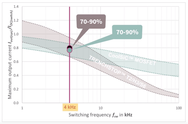
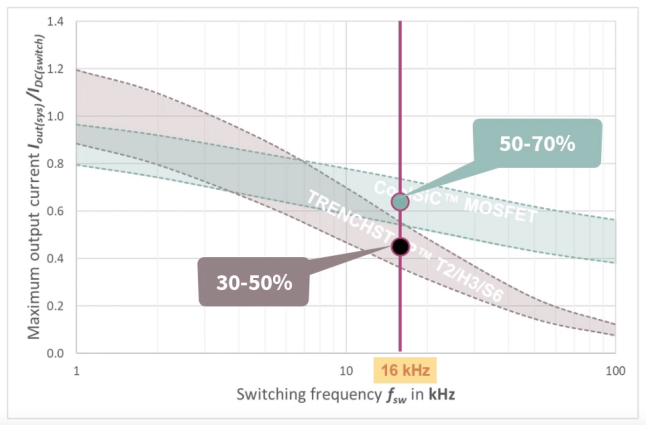
Based on the boundary conditions, the maximum output current of the half-bridge can be calculated and the conversion diagram can be drawn, which can quantify the power handling capability of the switching device. This figure shows the system output current as a function of switching frequency. The system output current is relative to the rated DC value of the device and is more commonly used than dealing with absolute maximum values.
2. Low frequency

Assuming that the device operates at 4KHZ, the IGBT can flow 70-90% of the rated current, and the SIC MOSFET is similar. Therefore, at low frequencies, the SIC MOSFET is selected to have a DC current rating similar to that of the IGBT.
For example, replace 40A IGBT and select 30-45mΩ SIC MOSFET. Depending on the actual current level, the semiconductor loss can be reduced by 20-50%.
3. High frequency

At a frequency of 16KHZ, SIC MOSFET can handle 50-70% of rated current, and IGBT only 30-50%.
Therefore, at the frequency of 16KHZ, the rated current of the SIC MOSFET is half that of the IGBT, and if the 40A IGBT is replaced, the SIC MOSFET of 60-80mΩ is selected.
SIC solution Benefits: Semiconductor losses are reduced by 50-70% depending on the current.
Summary
- At present, there is no general rule to correspond to the rating of IGBT and SIC MOSFET, which requires simulation and experiment to carry out specific analysis.
- Arough correspondence method based on the heat dissipation limit of the device is proposed.
- To choose 50 to 100 percent of the rated current of the IGBT as the rated current of the SIC MOSFET.
- Depending on the situation, SIC MOSFET can be designed in many ways to optimize performance, helping to reduce semiconductor losses by more than 50%, while also significantly improving switching frequency.
||Reprinted from Infineon, if there is infringement, please contact us to delete.


